CC340T DIGITAL PULSE TACHOMETER 


GENERAL

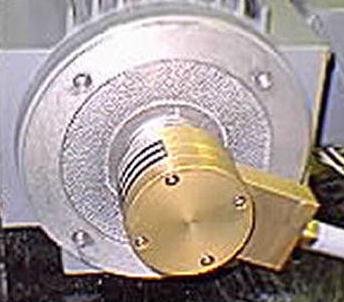
The CC340T Pulse Tachometer is a shaft mounted design for mill applications requiring a rugged, low cost and precision design.

APPLICATION

  • One tachometer can be mounted onto various shaft diameters and styles
  • No shaft coupling required
  • Unlimited shaft end-float motion
  • No alignment required when installing or replacing - Tilt (run out) Adjustment available on larger   diameter shafts
  • Higher accuracy feedback signal. No error signal introduced from coupling alignment errors


ELECTRICAL SPECIFICATIONS

Code

- Incremental, Optical

Cycles per Revolution

- Code Disc: 120, 240, 256, 270, 300, 500, 512, 540, 600, 1000, 1024, 1200, 2048

Supply Voltage

12 -15 VDC +/-5% or 20 -30 VDC

Supply Current (8830)

- CMOS + 150 mA max, 125 mA, typical

Output Signal

- Square wave, with following: 
- 2 Channels, phased 90 o Inverted Push-Pull Signal
 - Differentially Driven 
- In Quadrature, +/-2 o - With Marker Pulse

Output Voltage

- 5 VDC to 30 VDC

OA to OB Transition

- 15% Minimum Separation

Pulse to Any Pulse Accuracy

- +/-2 Minute of ARC (RMS)

Pulse to Adjacent Pulse

- +/-0.5 Minute of ARC

Temperature

- Operating, -40 o C to 100o C

Velocity Range

- 0 to 30,000 RPM

Speed Response

- Down to 0 RPM

Output Protection

- Power Supply Reversal


MECHANICAL SPECIFICATIONS

Housing

- NEMA 13 - Material: 6061 Aluminum, Anodized - Seal: O-Ring

Fasteners

- 303 Stainless Steel

Shaft Size

- 0.6250” (+.0000, -.0005)  303 Stainless Steel

Moment of Inertia

- 55 gm/cm 2

Bearing Life

- 2 x 10 8 revs at Rated Shaft Loading

Shaft Torque

- 0.5 to 1.0 oz.-in., Without Seal 
- 1.0 to 2.0 oz.-in., With Seal

Shaft Run

out

- 1.0 to 2.0 oz.-in. With Shaft Seal

Shock

- 50 G’s for 11msec Duration

Vibration

- 5 to 2000 Hz @ 20 G’s

Weight

- 3 lb.

HOW TO SPECIFY

DIGITAL PULSE TACHOMETER

Example:

CC340T 1024 ABZ 12 10A EN1 or M12 or C5
1 2 3 4 5 6 7 8

 CC340T = BASIC (Mill Duty) Design

1 = OUTPUT DESIGN
________340T = Shaft mounted tachometer

2 = CYCLES PER REVOLUTION
________XXXX = 240, 540, 600, 1000, 1024, 1200, 2048

3 = OUTPUT SIGNAL
________ABZ = Two channels with marker pulse

4 = OUTPUT VOLTAGE
________XX = 12 = +12 VDC standard; 5 = +5 VDC optional, 24 = +24 VDC optional,  30 =+30 VDC optional

5 = OUTPUT TERMINATION
________10A = Cam-lever hood connector - with removable Electronics Module
________3PT = 3 ft. Flexible Conduit with 2 ft. wire length after conduit with 1/2-14NPT male
________XPT = X ft. Flexible Conduit with 2 ft. wire length after conduit with 1/2-14NPT -  male threads for customer connection

MOUNTING SPECIFICATION GUIDE

TAPPED MACHINE CENTER HOLE MOUNTING

6 = SHAFT ADAPTER
      EN = inches

________EN1 = 1.125" dia shaft adapter with machine shaft 3/8, 1/2, 5/8, M10, M12, or M16 tapped center hole
________EN2 = 2.125" dia shaft adapter with machine shaft 3/8, 1/2, 5/8, M10, M12, or M16 tapped center hole
________EN3 = 2.375" dia shaft adapter with machine shaft 3/8, 1/2, 5/8, M10, M12, or M16 tapped center hole
________EN4 = 2.875" dia shaft adapter with machine shaft 3/8, 1/2, 5/8, M10, M12, or M16 tapped center hole

             MM = millimeters

________MM1 = 25mm shaft with machine shaft 3/8, 1/2, 5/8, M10, M12, or M16 tapped center hole
________MM2 = 30mm shaft with machine shaft 3/8, 1/2, 5/8, M10, M12, or M16 tapped center hole
________MM3 = 35mm shaft with machine shaft 3/8, 1/2, 5/8, M10, M12, or M16 tapped center hole
________MM4 = 40mm shaft with machine shaft 3/8, 1/2, 5/8, M10, M12, or M16 tapped center hole
________MM5 = 45mm shaft with machine shaft 3/8, 1/2, 5/8, M10, M12, or M16 tapped center hole
________MM6 = 50mm shaft with machine shaft 3/8, 1/2, 5/8, M10, M12, or M16 tapped center hole
________MM7 = 60mm shaft with machine shaft 3/8, 1/2, 5/8, M10, M12, or M16 tapped center hole
________MM8 = 80mm shaft with machine shaft 3/8, 1/2, 5/8, M10, M12, or M16 tapped center hole

TAPPED CENTER HOLE

7 = MOUNTING HARDWARE

3/8 = 3/8-16 1/2 = 1/2-13 5/8 = 5/8-11
M10 = M10 M12 = M12 M16 = M16

All hardware supplied with locking nylon insert.
Other machine shaft center tapped holes can be used, please specify.

8 = PRESSURE CLAMP MOUNTING

________C1 = 1.000" dia shaft with pressure clamp mounting
________C2 = 1.125" dia shaft with pressure clamp mounting
________C3 = 2.125" dia shaft with pressure clamp mounting
________C4 = 2.375" dia shaft with pressure clamp mounting with Tilt Adjustment
________C5 = 2.875" dia shaft with pressure clamp mounting with Tilt Adjustment
________C6 = 25mm dia shaft with pressure clamp mounting
________C7 = 30mm dia shaft with pressure clamp mounting
________C8 = 35mm dia shaft with pressure clamp mounting
________C9 = 40mm dia shaft with pressure clamp mounting
________C10 = 45mm dia shaft with pressure clamp mounting
________C11 = 50mm dia shaft with pressure clamp mounting
________C12 = 60mm dia shaft with pressure clamp mounting with Tilt Adjustment
________C13 = 80mm dia shaft with pressure clamp mounting with Tilt Adjustment

Other shaft diameters both English and Metric are available, special mountings available also.


PRODUCT DIMENSIONS

Dimensions = Inches (mm)

Back To Products Page

Carlen Controls
6560 Commonwealth Drive
Roanoke, VA 24018

Phone: 540-772-1736
For Sales Ext. 203
For Technical Assistance Ext. 201